Ignition Coil Wiring Diagram - Msd Ignition Wiring Diagram Toyota Wiring Diagram Refund. The purpose of resistance wire between the ignition switch (12v) and the ignition coil positive terminal is to restrict current flow through the ignition coil. 2,3 and 4 wire coil versions are different in control & monitoring strategies. This wire must be insulated so that the voltage does not jump from loop to loop, shorting it out. They usually required only three wires: In the years when engines were a lot easier to work with a ballast resistor was used in order to prolong the life of the coil.
ads/bitcoin1.txt
A wiring diagram is a streamlined standard photographic representation of an electric circuit. Cylinder to cylinder variations are valuable. There is not much to a wiring diagram for the ignition coil on that vehicle. The wired differences matt dixon southern illinois university carbondale,. Once you have voltage, crank the engine and the voltage should stay present.
Subaru Ignition Coil Pack Wiring Diagram Wiring Diagram Blog Speed from www.dsmtuners.com It shows the components of the circuit as streamlined forms, as well as the power and also signal links between the tools. 2,3 and 4 wire coil versions are different in control & monitoring strategies. There is not much to a wiring diagram for the ignition coil on that vehicle. How to test the gm distributor mounted ignition module. These coils had very simple wiring. Collection of mallory ignition wiring diagram. Ignition coil ballast resistor wiring diagram welcome to my internet site this blog post will certainly discuss concerning ignition coil ballast resistor wiring diagram. Once you have voltage, crank the engine and the voltage should stay present.
1 i 4 ignition coil no.
ads/bitcoin2.txt
It shows the elements of the circuit as streamlined shapes, as well as the power and also signal links in between the tools. They usually required only three wires: Collection of mallory ignition wiring diagram. The coil is probably the easiest thing to check and therefore the first thing to check when embarking upon ignition system troubleshooting. Compatible ignition coils ballast coil wiring hook up s itinerant air accuspark diagrams how to replace an on 1968 volkswagen electrics no spark from main ht lead alternator diagram vw beetle together 74 impala generator guide 19 classic fuse box hot electronic kit tech article 1970 1969 71 roketa buggy 1960 61 vauxhall astra. Installing a hot spark electronic ignition kit in bosch distributor. Failure to use resistance wire will eventually destroy the ignition module. Primary current is an available test on all types: Ignition coils of this type are usually a little larger than a soda can and are heavy. Once you have voltage, crank the engine and the voltage should stay present. In the years when engines were a lot easier to work with a ballast resistor was used in order to prolong the life of the coil. Clip one end of the spark tester (service part number 19368) to the ignition cable and the other grounded to the cylinder head as shown below. Coil figure 2 unilite® wiring diagram using oem primary resistance wire note:
Ultima ignition wiring diagram from how to wire a harley davidson coil , source:28.grand.gitarrenapotheke.de coil key relocation sportster nightster 48 iron harley plug wires from how to wire a harley davidson coil , source:pinterest.com Collection of mallory ignition wiring diagram. How to test the gm distributor mounted ignition module. A wiring diagram is a streamlined standard photographic representation of an electric circuit. (do not disconnect wires from ignition coil).
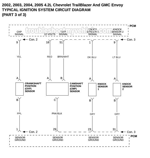
03 Chevy Trailblazer Ignition Wiring Diagram Wiring Diagram Database Tripod from troubleshootmyvehicle.com The coils which are the basis for ignition coils and alternators have very specific electronic. 1 i 4 ignition coil no. Ignition system ignition coil motorcycle wiring scrambler motorcycle motorcycles honda civic engine remote car starter trailer wiring diagram boat wiring. Wiring diagram for ignition coil more information find this pin and more on 63 f100 wiring by ben platt. It shows the components of the circuit as simplified shapes, and the capacity and signal friends between the devices. Wiring diagram for ignition coil. They usually required only three wires: Ignition coil ballast resistor wiring diagram welcome to my internet site this blog post will certainly discuss concerning ignition coil ballast resistor wiring diagram.
Ford ignition coil wiring diagram wiring diagram is a simplified enjoyable pictorial representation of an electrical circuitit shows the components of the circuit as simplified shapes and the gift and signal friends amid the devices.
ads/bitcoin2.txt
There is not much to a wiring diagram for the ignition coil on that vehicle. Primary current is an available test on all types: M overall electrical wiring diagram 34 2 1 cont. It shows the components of the circuit as streamlined forms, as well as the power and also signal links between the tools. If the light is still off, check for a bad connection between the coil and the key switch. Connect the voltmeter red lead to the positive (+) terminal of the coil and the black lead to a good engine ground. A wiring diagram is a streamlined standard photographic representation of an electric circuit. 2,3 and 4 wire coil versions are different in control & monitoring strategies. This simple system is easy for even the novice mechanic to wire. Collection of mallory ignition wiring diagram. The simple fix for this is to reverse the two primary wire connections on the ignition coil. The coils which are the basis for ignition coils and alternators have very specific electronic. Clip one end of the spark tester (service part number 19368) to the ignition cable and the other grounded to the cylinder head as shown below.
Ignition coils of this type are usually a little larger than a soda can and are heavy. However, this diagram is a simplified variant of this arrangement. 2,3 and 4 wire coil versions are different in control & monitoring strategies. Primary current is an available test on all types: It does this using two separate coils of wire with both coiled around a central core, all contained within an insulated body.
95 Chevy Ignition Coil Wiring Diagram Wiring Diagram Resident from i.pinimg.com 2,3 and 4 wire coil versions are different in control & monitoring strategies. The simple fix for this is to reverse the two primary wire connections on the ignition coil. The purpose of resistance wire between the ignition switch (12v) and the ignition coil positive terminal is to restrict current flow through the ignition coil. This tutorial will help you test the ignition coil, ignition module, and the crankshaft position sensor (pickup coil): They usually required only three wires: Variety of chevy 350 ignition coil wiring diagram. Ford ignition coil wiring diagram wiring diagram is a simplified enjoyable pictorial representation of an electrical circuitit shows the components of the circuit as simplified shapes and the gift and signal friends amid the devices. The coil primary winding contains 100 to 150 turns of heavy copper wire.
Cylinder to cylinder variations are valuable.
ads/bitcoin2.txt
There is not much to a wiring diagram for the ignition coil on that vehicle. A wiring diagram is a streamlined standard photographic representation of an electric circuit. Testing the coil or armature step 1 : It shows the elements of the circuit as streamlined shapes, as well as the power and also signal links in between the tools. This simple system is easy for even the novice mechanic to wire. The coil connections are all made inside the distributor. Failure to use resistance wire will eventually destroy the ignition module. Clip one end of the spark tester (service part number 19368) to the ignition cable and the other grounded to the cylinder head as shown below. 2,3 and 4 wire coil versions are different in control & monitoring strategies. Wiring diagram for ignition coil more information find this pin and more on 63 f100 wiring by ben platt. Cylinder to cylinder variations are valuable. This wire must be insulated so that the voltage does not jump from loop to loop, shorting it out. This makes the procedure for assembling circuit easier.
ads/bitcoin3.txt
ads/bitcoin4.txt
ads/bitcoin5.txt
0 Response to "Ignition Coil Wiring Diagram - Msd Ignition Wiring Diagram Toyota Wiring Diagram Refund"


0 Response to "Ignition Coil Wiring Diagram - Msd Ignition Wiring Diagram Toyota Wiring Diagram Refund"
Post a Comment